


AIL15 - Monitoring Of Presence / Drop-out Of 3 Phase Voltages In The Low Voltage Network

- CLIENT: Schrack Technik
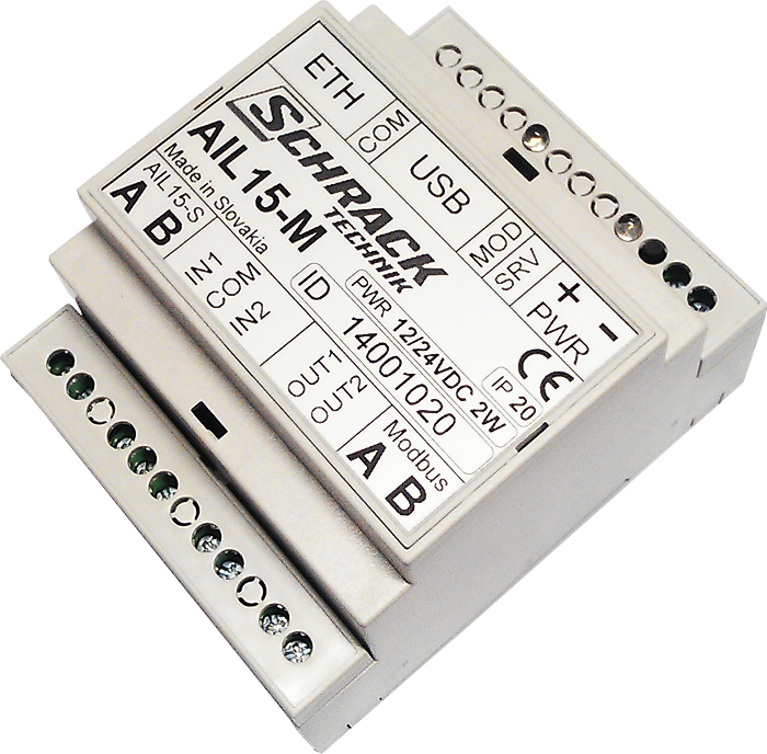
The product consists of two parts. AIL15-M in tandem with AIL15-S is a modular system designed to monitor 1 to 16 pieces of three-phase outputs in the low voltage network. The AIL15-M measurement unit is evaluating, processing and publishing data gathered from AM15-S.
AIL15-M
AIL15-M concentrator is gathering data from up to 16 pieces of AIL15-S measurement units. The measured data from every measurement unit - voltage, current, effective power, idle power - is calculated and evaluated. The output values are published through the RS-485 Modbus interface and sent to the FTP server.
Communication interfaces:
-
Ethernet RJ45
-
Modbus RS-485
-
without galvanic separation
-
communication speed 115 200 Bd 8N1
-
AIL15-S RS-485
-
with galvanic separation
-
5000 V isolation voltage according to UL1577
-
proprietary, address protocol
-
communication speed 115 200 Bd 8N1
Power supply:
-
+12 V to +24 V DC 2 W
-
power supply should be backed-up in case of drop-outs to prevent data loss
Expendable interfaces:
-
USB for configuration
-
2x digital input (galvanic separation)
-
1x output signal relay
-
1x adjustment button
Technical parameters
|
POWER SUPPLY |
+12 V to +24 V DC |
|
POWER |
2 W |
|
BUILT-IN POWER SUPPLY CURRENT PROTECTION |
100 mA return fuse |
|
COMMUNICATION OUTPUT INTERFACE FOR AIL15-S |
Galvanically separated RS-485 |
|
COMMUNICATION SPEED THROUGH RS-485 |
115 200 Bd, 8N1 |
|
RS-485 ISOLATION STRENGTH |
5000 V RMS / 1 min. according to UL1577 |
|
COMMUNICATION OUTPUT INTERFACE MODBUS |
Galvanically non-separated RS-485 |
|
COMMUNICATION SPEED THROUGH RS-485 |
115 200 Bd, 8N1 |
|
MECHANICAL DESIGN |
plastic box to 70 mm DIN bar |
AIL15-S
AIL15-S measurement unit is designed to measure voltage, current, effective power and idle power in transformer stations, low voltage distribution points etc. Measured data is sent through RS-485 serial interface of the AIL15-M concentrator. It is possible to connect up to 16 pieces of AIL15-S measurement units to the serial interface.
Inputs:
-
3 voltage inputs for direct measurement of 230 V/50 Hz with shared zero conductor (one three-phase output)
-
0,5 m wires with double isolation non-detachable from the box
-
three wires with implemented protection impedance and one zero conductor
-
voltage inputs are conform with STN EN 61010-1: max. 300 V, CAT IV
-
-
3 current inputs 5 A/50 Hz with shared zero conductor for indirect measurement for external MTP
-
Connection to 6 screw clamps with 2,5 mm2 maximal section
-
Output interfaces:
RS-485 with galvanic separation, connected to Phoenix QC 1/4-ST-BUS connector
-
communication with AIL15-M, proprietary, address protocol
-
Address configurable by a switch in the range of 1 to 16
-
115 200 Bd 8N1 communication speed
-
5000 V isolation voltage according to UL1577
Power supply:
+8 V to +24 V DC, 70 mA nom. current, Phoenix QC 1/4-ST-BUS connector
-
Integrated galvanically separated DC/DC convertor
-
3750 V DC isolation voltage
-
Power supply bus for AIL15-S has to be supplied by galvanically separated power supply with minimum 3000 V DC isolation strength
Measurement properties:
-
Measurement of effective values of U and I in all phases, 1/s in the 2 precision class
-
Measurement of effective and idle power P and Q by particular phases, 1/s in the 2 precision class
Technical parameters
|
POWER SUPPLY VOLTAGE |
+8 V to +24 V DC |
|
POWER SUPPLY CURRENT |
nom. 70 mA |
|
BUILT-IN POWER SUPPLY CURRENT PROTECTION |
100 mA return fuse |
|
ISOLATION STRENGTH OF GALVANICALLY SEPARATED POWER SUPPLY |
3 750 V DC |
|
RECOMMENDED POWER SUPPLY FOR MAX 16 PCS OF AIL15-S |
MEAN WELL DR-15-12 set to 10,8 V |
|
COMMUNICATION OUTPUT INTERFACE |
Galvanically separated RS-485 |
|
COMMUNICATION SPEED THROUGH RS-485 |
115 200 Bd, 8N1 |
|
RS-485 ISOLATION STRENGTH |
5000 V RMS / 1 min. according to UL1577 |
|
L1, L2, L3 VOLTAGE INPUTS |
3x 230 V AC |
|
MAXIMAL INPUT VOLTAGE |
max. 300 V, CAT IV, according to STN EN 61010-1 |
|
VOLTAGE INPUTS INPUT IMPEDANCE |
880 kOhm |
|
CURRENT INPUTS |
3x 5 A AC, galvanically connected |
|
MAXIMAL INPUT CURRENT |
max. 12 A AC |
|
INPUT IMPEDANCE OF L1, L2, L3 CURRENT INPUTS |
0,025 ohm |
|
MEASURED VALUES |
U, I, P, Q in three phases |
|
U, I, P, Q MEASUREMENT INTERVAL |
1 s |
|
OPERATION TEMPERATURE RANGE |
-25 °C to 70 °C |
|
MECHANICAL DESIGN |
plastic box, dimensions 110 x 57 x 45 mm |
